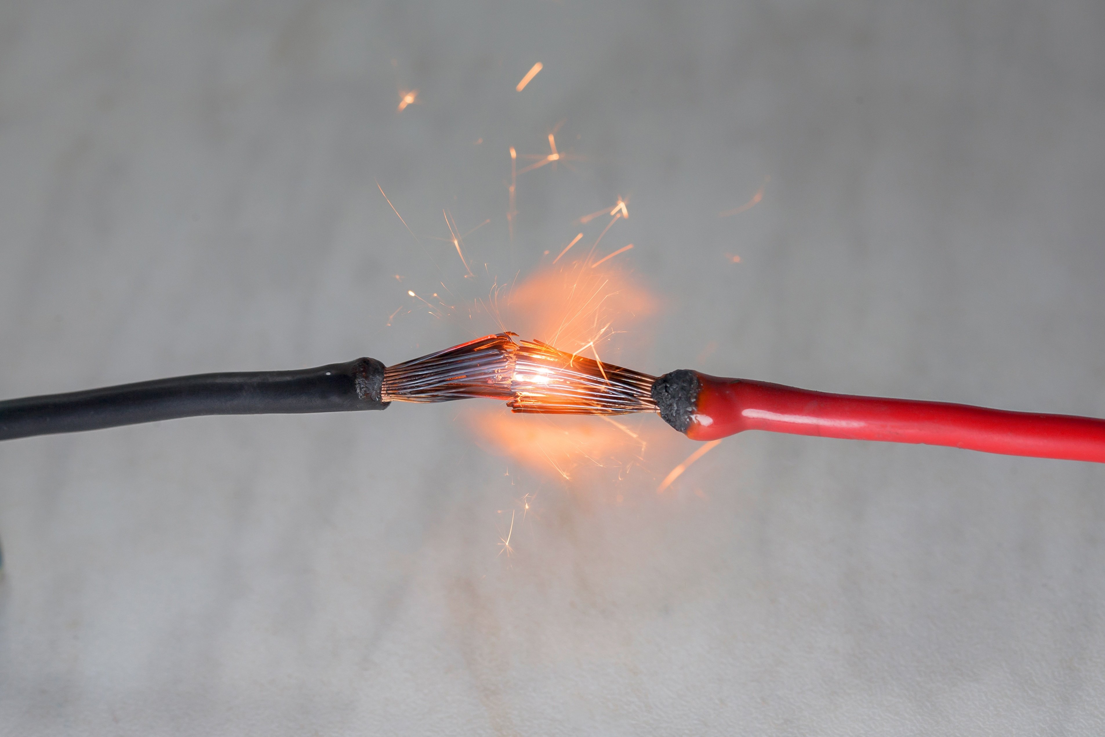
The number one cause of electrical fires on boats is wiring complications from direct current (DC) circuits. The reason is that direct current wiring encourages individuals who may not know what they’re doing to try a repair themselves.
For example, you need a new switch panel but don’t have the extra funds to pay someone to do the work, so you attempt it yourself. Or you get a new fish finder for Christmas and don’t want to wait until Spring to have your mechanic install it, so you try it.
There’s nothing wrong with doing things yourself to save money or learn a new skill. Not everyone has a friend or family member to help with repairs. However, doing things correctly is essential so you are not forced to swim back to shore one afternoon or left frantically calling the fire department because your boat and dock are set ablaze.
Let’s review everything you need to know about DC marine wiring and more.
Comparing Different Types of Wiring
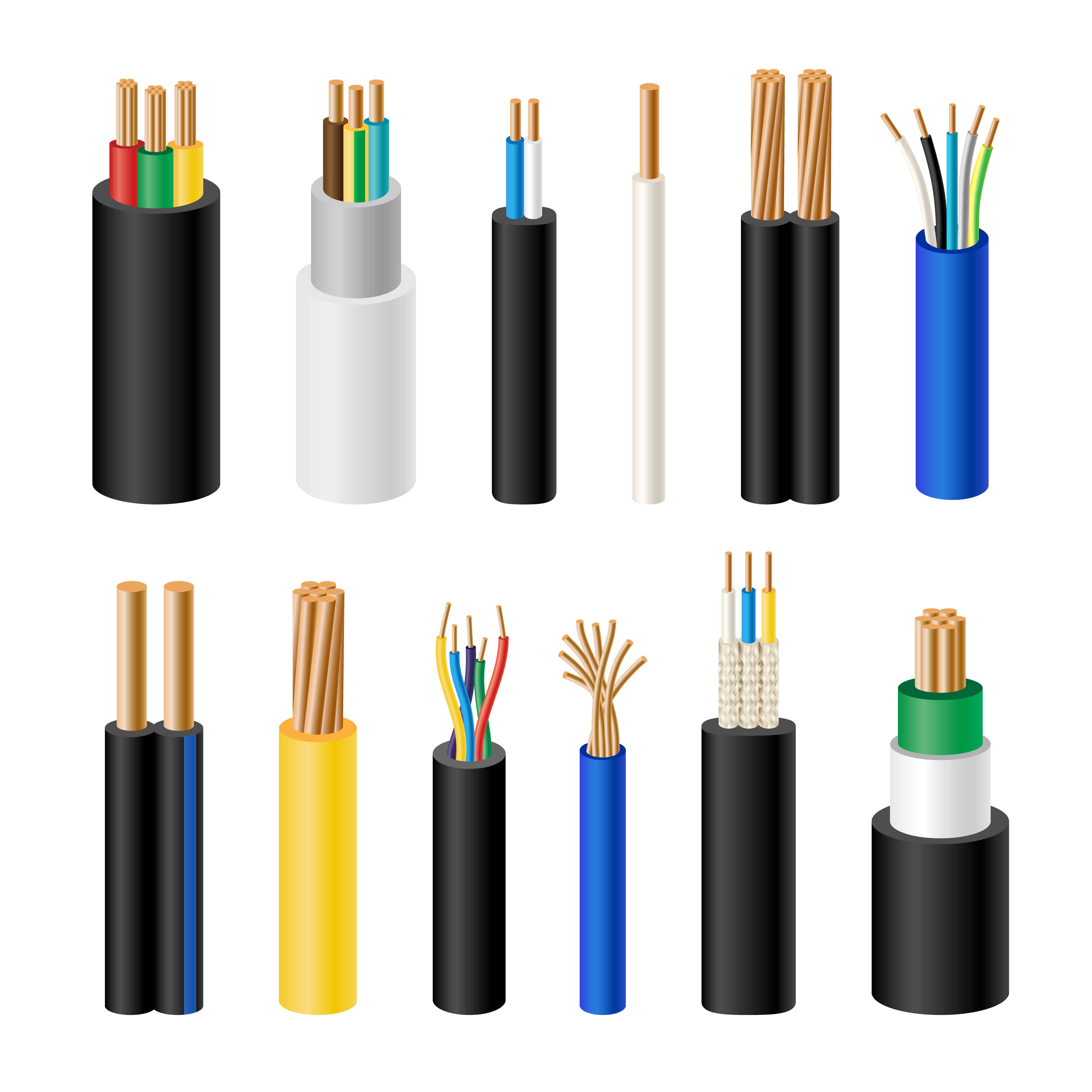
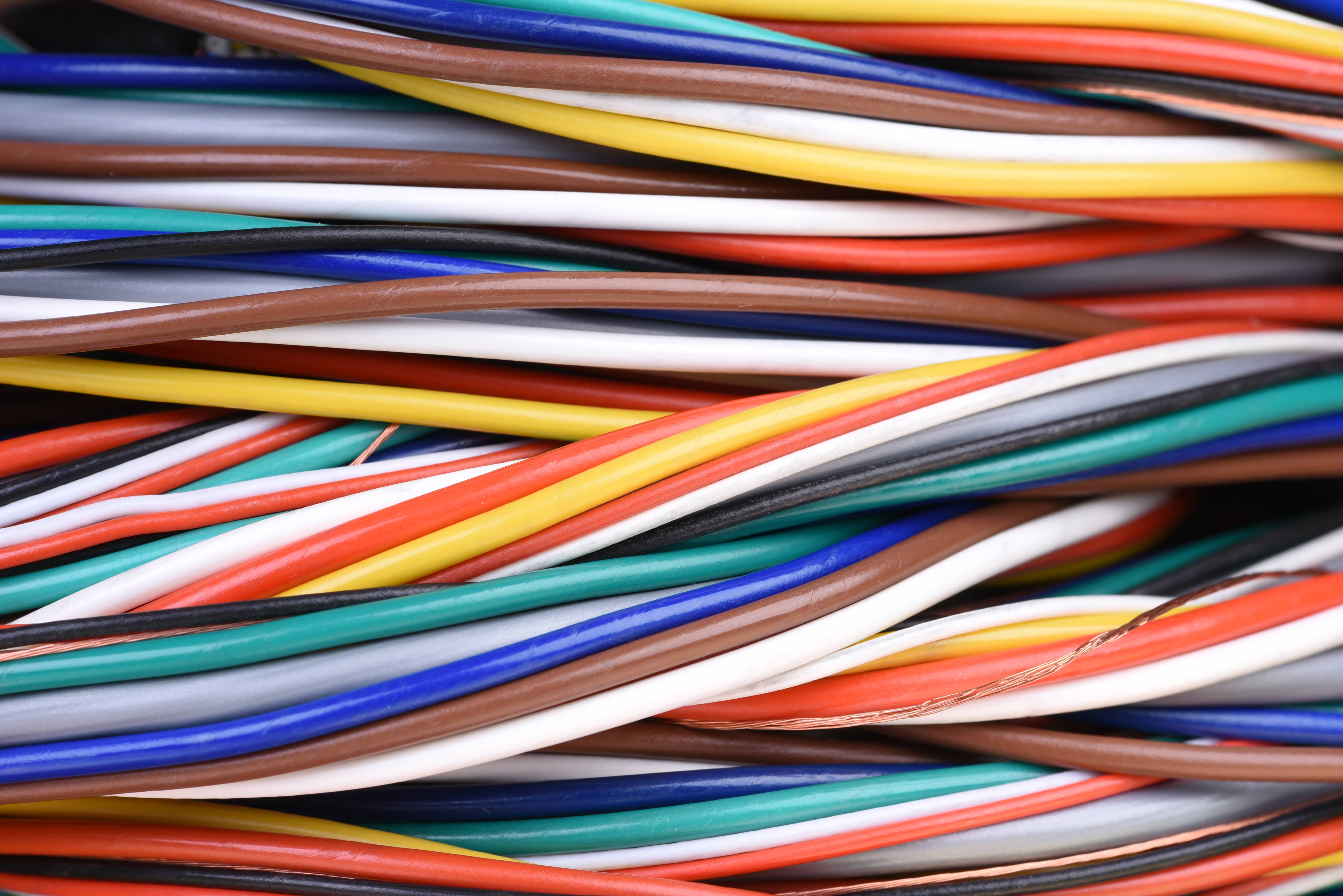
There are many different types of wire, more than you would ever care to know. For this article, we’ll break it down into marine and automotive wiring. The main difference between automotive and marine wiring is corrosion protection. Marine wiring is coated in tin to prevent corrosion and oxidation, whereas automotive wire is just copper. Both types can be used on boats; however, there are stipulations.
Because tin-coated marine wiring is better at resisting corrosion, it must be used in the bilge or other areas with spray or dripping due to increased moisture content. Marine wiring also has an oil-resistant jacket so it can be used in engine bays.
If you’re on a budget, regular copper wire can be used above deck, but marine wiring throughout is still preferred even though it will cost more.
SAE vs. AWG Wire
Marine wiring is made to American Wire Gauge (AWG) standards, whereas automotive wiring is made to Society of Automotive Engineering (SAE) standards. The difference is mostly size. AWG is around 12 percent larger than SAE wire. This allows it to carry more current and experience less voltage drop. Both types can be used in marine applications, but you’ll need to pay more attention when selecting the correct size, which we will cover later in the article.
Single vs. Multi-Stranded Wire
Unlike residential wire that is single-strand, automotive and marine wiring is multi-strand. Single strand is used on AC circuits, whereas multi-strand is used on DC circuits. Multi-strand offers better protection from vibrations.
How to Choose the Correct Size DC Marine Wiring
Choosing a wire size is one of the most critical parts of wiring electronics on a boat. The wire’s size, referred to as gauge, dictates the current or voltage it can carry. If a wire is too small, the circuit can overheat causing the wire to melt and increasing the potential for fire. If you use a wire that’s too large, you’ll waste money and add unnecessary weight. This is why it’s essential to choose the correct size.
When choosing a size, you’ll need to consider the run from the power source to the accessory, the amount of power required, and objects around the wire that may cause extra heat, like the engine. You’ll also need to factor in bundled wires, as groups of wires together create more heat.
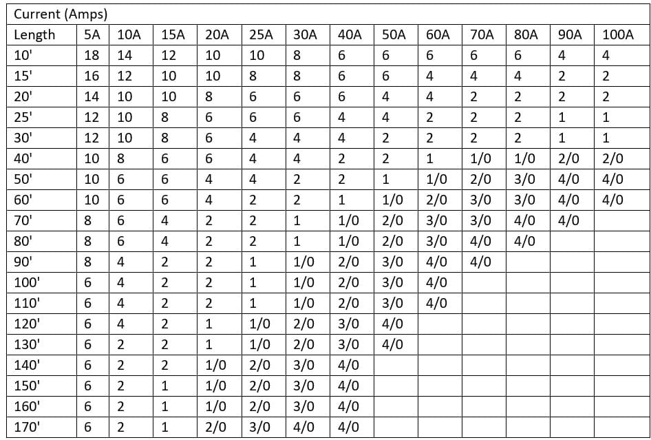
Critical Applications with 3% Voltage Drop
The following chart assumes a 3% voltage drop and should be used with critical applications such as running lights, switch panels, etc.
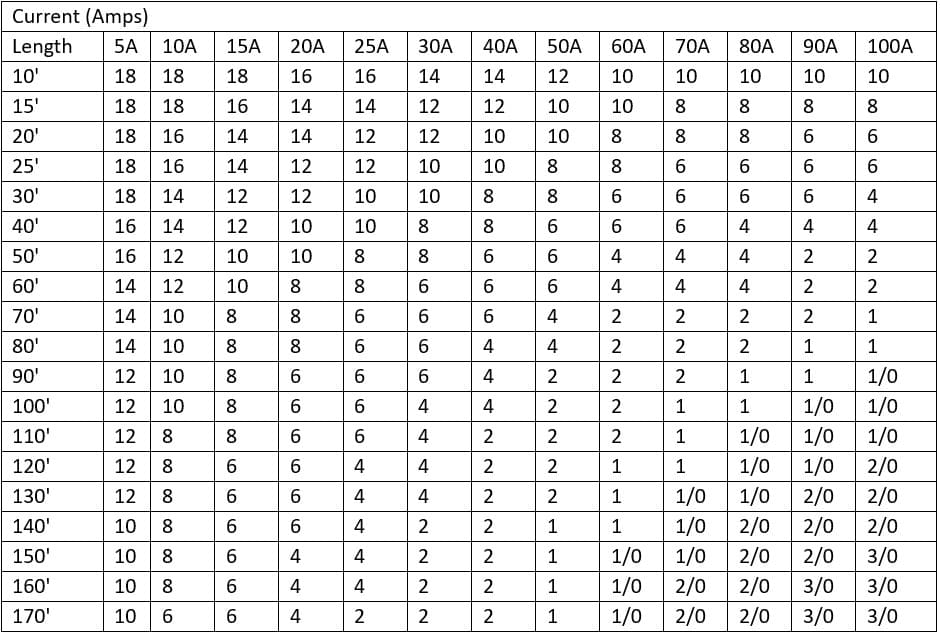
 Non-Critical Applications with 10% Voltage Drop
The following chart assumes a 10% voltage drop and should be used with non-critical applications such as fish finders, navigation, etc.
Please note that when routing wires through an engine bay, you must reduce the maximum current by 15 percent. If bundling wires, assume the following. Bundles of 3 should reduce current by 30 percent, bundles of 4-6 should reduce current by 40 percent, and bundles of 7-24 should reduce current by 50 percent.
Marine Wire Color Standards
When dealing with electronics on your boat, it’s helpful to get a basic idea of what specific wire colors represent. In the chart below, you see standards as outlined by the American Boat and Yacht Council (ABYC). However, as a previous owner could have rewired the boat using different colors, it should only be used as a guide. The sure way to know what color of wire a particular function represents is to test.
| Color | Item | Application |
| Green/Green w/Yellow Stripe | DC Grounding Conductor | Bonding Wires (insulated) |
| Yellow or Black or Black w/Yellow Stripe | DC Negative Conductor | Negative Mains |
| Red | DC Positive | Positive Mains |
| Yellow w/Red Stripe | Starting Circuit | Starting Switch to Solenoid |
| Brown w/Yellow Stripe or Yellow | Bilge Blowers | Fuse or Switch to Blower |
| Dark Gray | Navigation Lights | Circuit Breakers or Switch To Lights |
| Dark Gray | Tachometer | Tachometer Gauge and Sender |
| Brown | Generator Armature | Generator Armature to Regulator |
| Brown | Alternator Charge Light | Generator Terminal or Alternator Aux Terminal to Regulator |
| Brown | Pumps | Circuit Breakers or Switch to Pumps |
| Orange | Accessory Feed | Amp Mtr to Alt or Gen Output & Acc Circuit Breaker & Switches |
| Orange | Common Feed | Distribution Panels To Accessory Switches |
| Purple | Ignition | Ignition Switch to Coil & Electrical Instrument |
| Purple | Instrument Feed | Distribution Panel To Electrical Instruments |
| Purple | Main Power Feed | Positive Mains (particularly un-fused) |
| Dark Blue | Cabin and Instruments | Circuit Breakers or Switch to Lights |
| Light Blue | Oil Pressure | Oil Pressure Gauges & Senders |
| Tan | Water Temp | Water Temp Sender To Gauge |
| Pink | Fuel Gauge | Fuel Gauge Sender to Gauge |
| Green w/Stripe | Tilt Down/Trim in | Tilt and Trim Circuits |
| Blue w/Stripe | Tilt Up/Trim Out | Tilt and Trim Circuits |
Connecting Wires
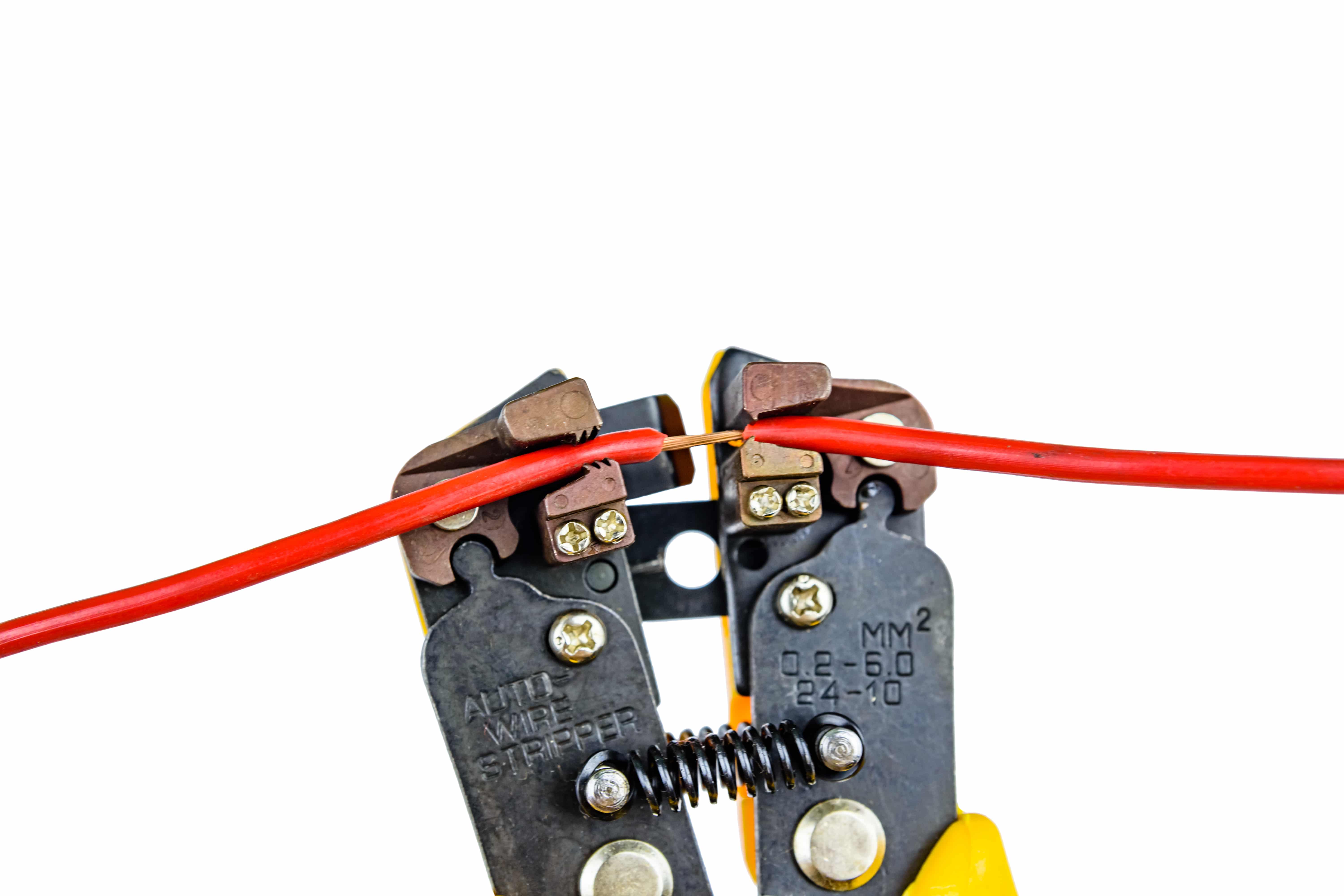
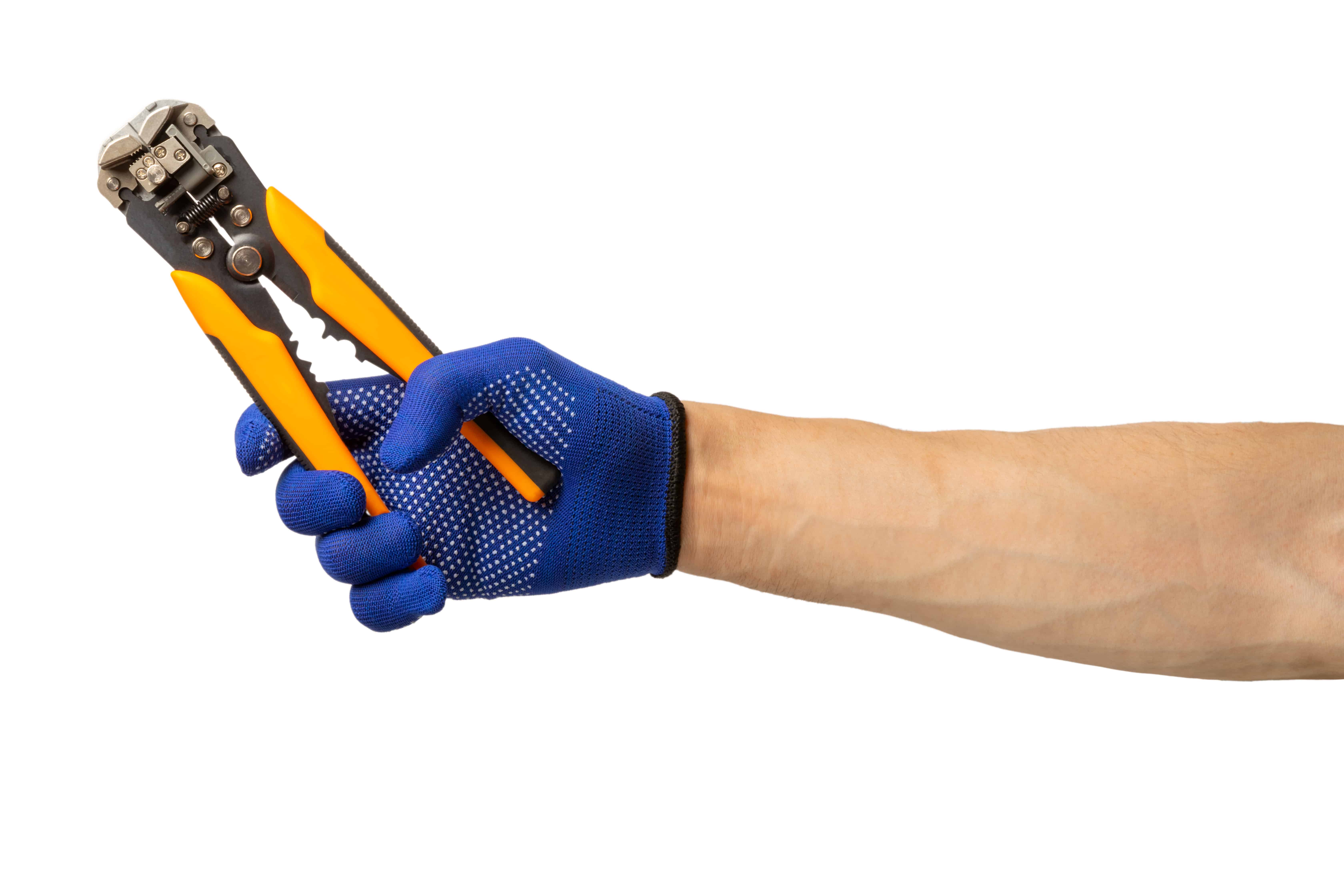
There are a few different ways to connect wires together or to an accessory. The most common ways are crimping and soldering. According to the ABYC, wires should be connected manually via crimp joints that are not prone to breaking due to stress and fatigue.
To crimp wires, you will need a set of wire strippers, crimping pliers, and crimp connectors. There are several different styles of crimp connectors. The correct style varies by application. Marine crimp connectors should also have heat-shrink tubing integrated to keep out water. Following is a list of commonly used crimp terminal connectors.
Spades – These quick connect/disconnect terminals are commonly used for relays and other components. They come in male and female as well as different widths.
Fork – Used to connect wires to clamping hold-downs. It serves the same purpose as a ring terminal but is easier and faster to install.
Ring – Also used to connect wires to a clamping hold-down. It is more secure than a fork-style connector.
Butt – Used for wire-to-wire connections when running in a continuous line.
Cap – Connects multiple splices. Wires will make a 90-degree turn in and out of the connector.
Bullets – Like spades, these connect/disconnect wires quickly. They are round, whereas spades are mostly flat.
Taps – Used for tapping a wire into an existing circuit. No splicing is required.
Installing Crimp-Style Wire Connections
To attach a crimp-style connector, you’ll first need to strip back some of the jacket from the wire. Then, insert the bare end of the wire into the connector and crimp using an appropriate crimp tool. Once finished, give the wire a good tug to ensure it’s seated properly. Lastly, use a heat gun to seal the heat shrink around the wire (if applicable).
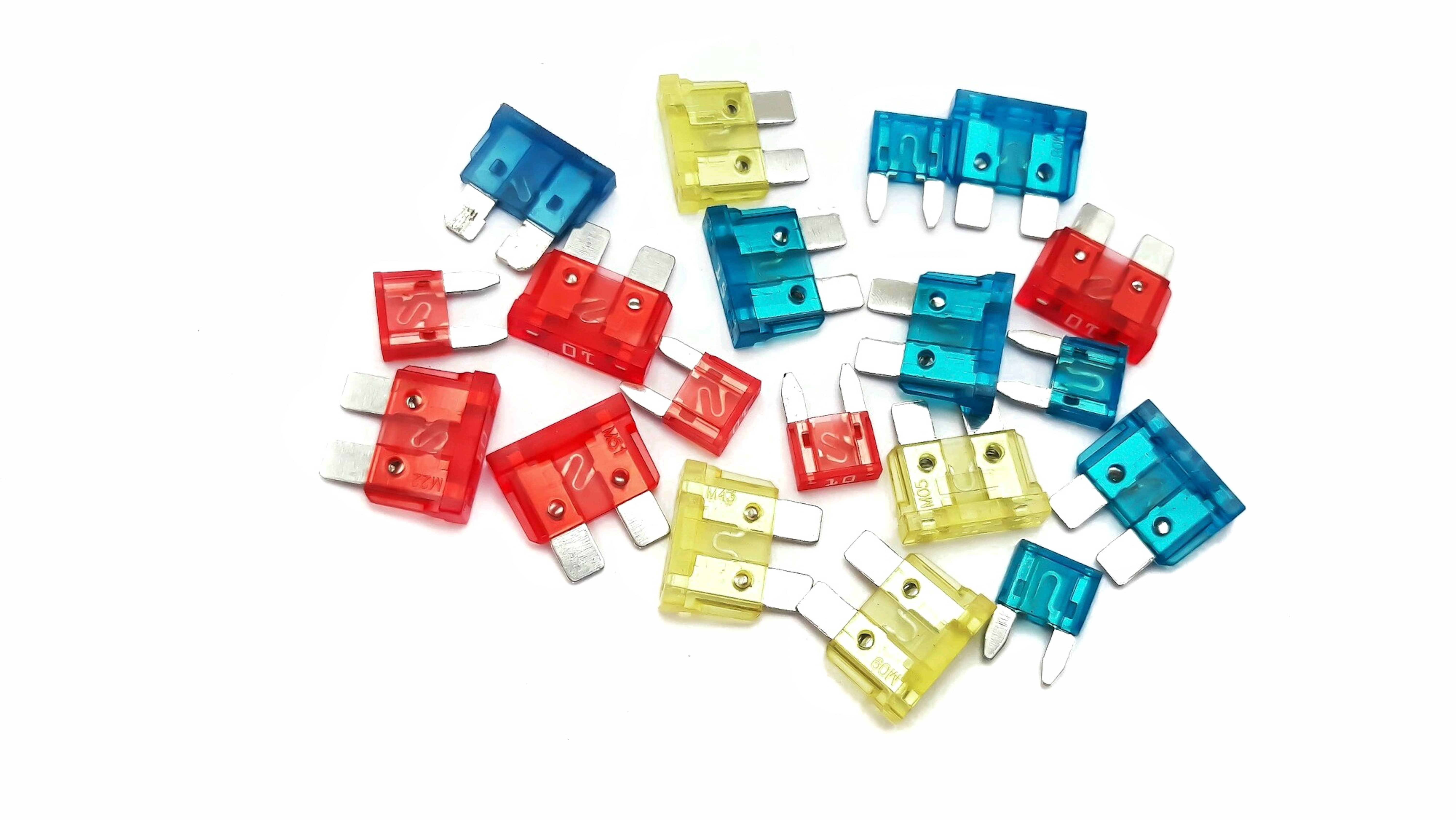
Please note that there are multiple sizes of wire connectors coded by color. Most connectors will fit a range of different size wires.
Red: 22-18 Gauge
Blue: 18-16 Gauge
Yellow: 12-10 Gauge
ABYC Standards
Aside from wire size and color, there are other standards outlined by the ABYC that you should consider when doing electrical repairs on a boat.
Supports: Wire supports such as ring clamps or cable ties should be used in 18” increments to avoid excess flexing.
Chafing: When passing wires through structural material, you must protect them using wire loom to prevent nicks and frays.
Terminal Limit: When attaching multiple ring terminals to a stud, the highest ampacity should be installed first, followed by a maximum of up to three other terminals.
Basic Troubleshooting Steps
If you’ve owned a boat long enough, you’ll likely have electrical problems at some point. Thankfully, most electrical issues can be fixed with basic tools and an understanding of how circuits work. Here’s a list of some common tools you may find helpful.
- Multimeter or Circuit Tester Light
- Electrical Tape
- Wire Connectors
- Wire Loom
- Electrical Contact Cleaner
Fuses
The fuse box is the first place to look when an accessory or circuit does not have power. Every circuit on the boat should have fuse protection. If the circuit is wired correctly, this should be the first part that fails. There are many different types of fuses, so you’ll want to familiarize yourself with the kind on your vessel. It can be difficult to tell if a fuse has blown while it’s installed, so it’s recommended to remove it first before visual inspection.
Ground
The second place to look when troubleshooting is your ground. For an accessory to work properly, it must have both power and ground. Unfortunately, testing the ground can be challenging for those not experienced using a multimeter. If you are, you can look for continuity between the power and ground circuits; if not, it’s best to inspect the ground visually and physically. First, ensure the wire is secure to the ground stud and the nut is tight. Then, check for corrosion. If all else fails, remove the ground terminal, clean the area, and reinstall.
Corrosion
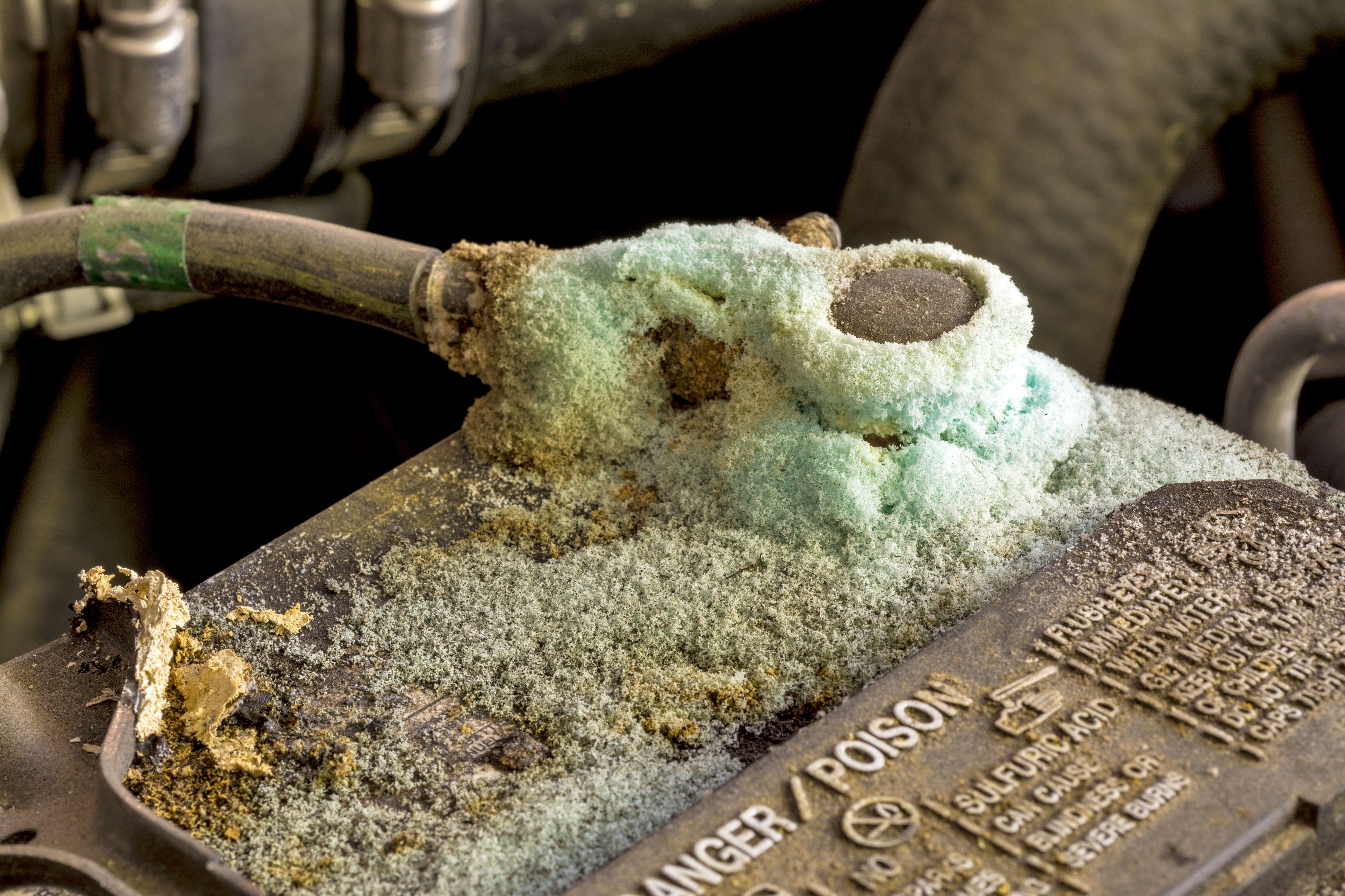
It’s no secret that water and electricity don’t mix. However, dealing with this is just a part of life for boaters. Corrosion can cause a break in the electric circuit, leading to a power loss. Over time, it eats away at the wire. If you catch corrosion early enough, you can usually clean it with some contact cleaner and a nylon brush, but if it’s been left for too long, you may need to replace the damaged component. Corrosion is easy to spot as it shows up as a greenish-white powder. If you see any, it’s important to repair the entire area, preventing future occurrences.
Shorts
Many things, including corrosion, can cause a short. By definition, it’s a break or loss of power in a circuit. Another common cause of this issue is fraying, caused by chafing. If a wire is not supported properly when passing through metal structures, the wire jacket can rub on the sharp edges of the object. Over time, this will cause the jacket to wear off and expose bare wire, leading to breaks or shorts. Per ABYC, all wires passing through structural material must be protected with loom and supported every 18”.
Crimping
When I first started doing my own repairs, I always had issues with crimp connectors. The problem with crimp connections is that you can’t see inside the connector to ensure a good bond. It takes practice before you start to get it right. If you find yourself struggling, pay attention to the crimp manufacturer’s specifics, such as the amount of jacket to strip and the force to be applied with the crimp tool. Also, don’t forget the pull test to ensure both wires are seated properly. If unsure of the bond, you can test it by applying power to one side of the wire and testing the opposite end with a multimeter or test light.
Battery
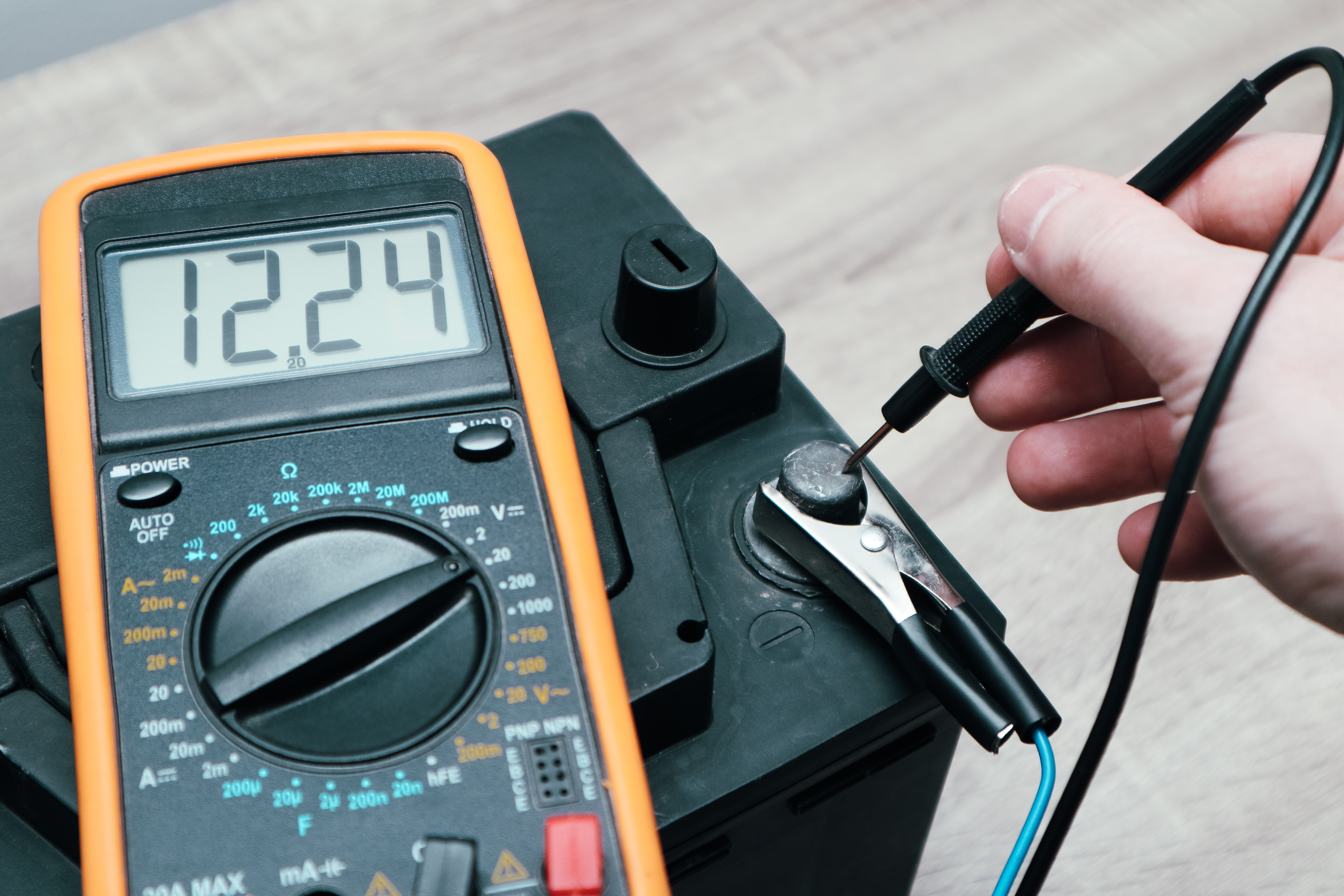
The battery onboard your boat is very similar to the battery in your car. You’ll run into issues powering your accessories if you don’t have a good charge. There’s always the option of removing the battery and taking it to an auto parts store to be tested, but if you have a multimeter, you can do this yourself. You’ll want a minimum of 12 VDC at the positive battery terminal, but ideally, you’ll have up to around 13/14 VDC. If you don’t, this is likely causing your issue, so it must be charged. If you still have low voltage after charging, you likely have bad cells and must replace the entire battery.
Share some of your DC wiring tips in the comments below!


[…] Understanding the Basics of DC Marine Wiring […]
[…] this article, we’ll review everything you need to know about replacing boat trailer lights, from wiring to all the different […]
[…] only marine wire when routing power to and from the pump and switch. Since most pumps draw upwards of 10 amps, […]
[…] car stereo uses the same power source as a marine stereo, 12 VDC. Therefore, technically, a car stereo will work in a boat. However, this is not advisable as they […]